VFD Input Current vs Output Current: Why the Readings Differ
- 2026 Nov 18
VFD input current vs output current: see why amps differ at low speed, how to compare readings and when to investigate a supply- or motor-side change.
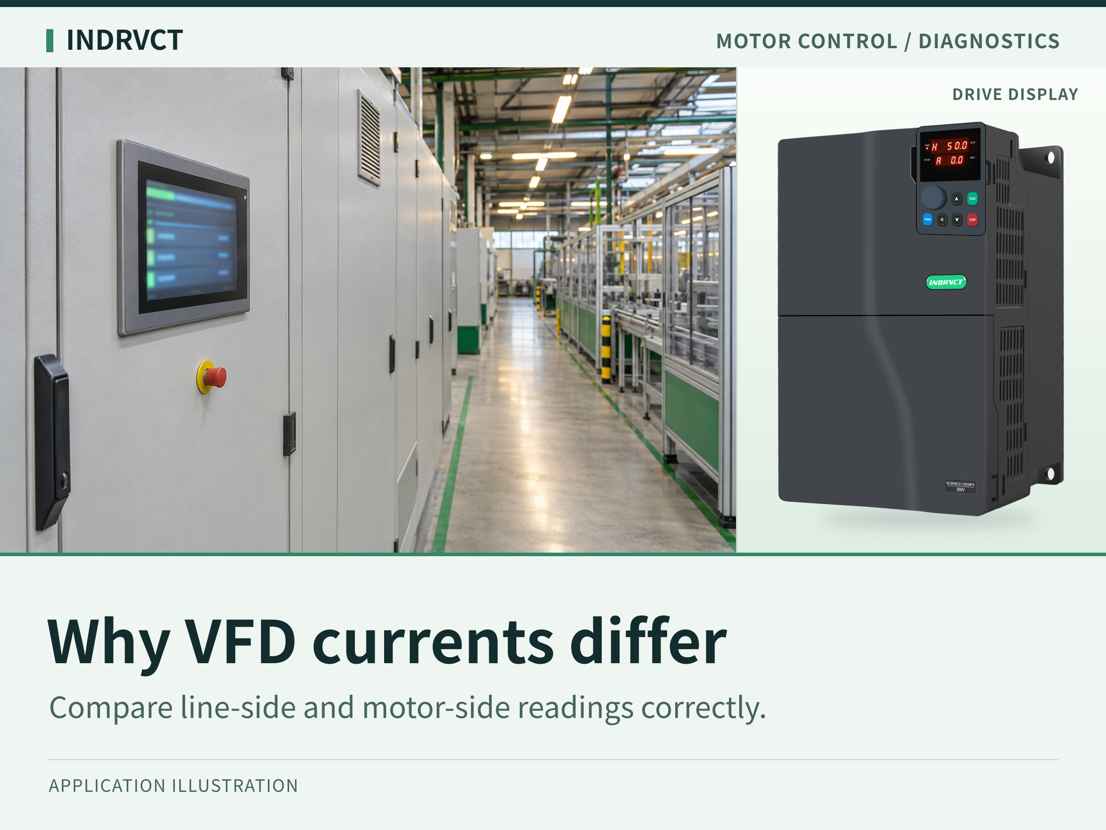
A variable frequency drive (VFD) can draw less current from the supply than it delivers to the motor, particularly at some low-speed operating points. That difference alone does not indicate a bad drive, and the two readings do not have to match. To interpret the difference, verify where each value came from, whether the machine was in the same operating state and how each instrument reported current. Then compare each side to its own limit and to a healthy baseline.
Identify the Two Current Readings
The input current is drawn from the source feeding the drive. A reading from a cabinet feeder is not necessarily the same thing: that feeder may also supply a cooling fan, transformer, brake control or another drive. The output current is the current the inverter supplies to the motor circuit. A single motor's branch current, the drive's total output reading and the current on the upstream feeder represent different boundaries. Write down which circuit each number describes before putting them in the same report.
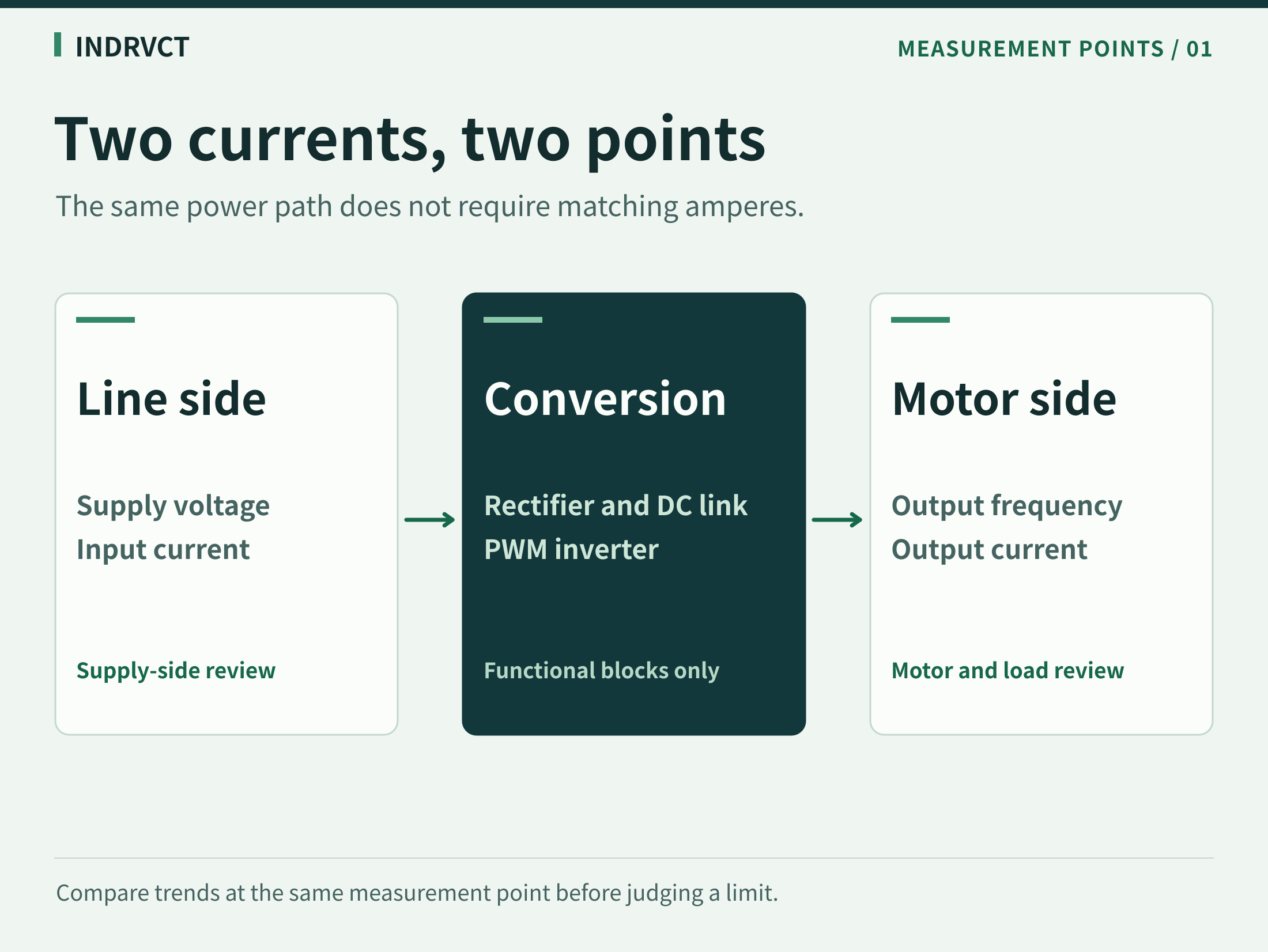
In a conventional AC-to-AC VFD with a DC link, the input stage converts the supply to DC and the inverter stage synthesizes variable-frequency output for the motor. The supply and motor sides can operate at different effective voltages and have different power factors and waveforms. When the machine is steadily motoring, the real input power into the drive includes the motor-side electrical power and drive losses. That relationship concerns watts, not amperes. It does not require input amperes to exceed output amperes.
Why Motor Current Can Be Higher at Low Speed
The inverter changes its output voltage and frequency to operate the motor. At a low-speed operating point, the effective motor voltage may be below the line voltage, while the motor still needs current to build magnetic flux and deliver the torque demanded by the load. The line and motor side also have different power factors; a diode-front-end drive can draw a distorted line current. Amps alone therefore do not tell you the active power on either side.
Consider a conveyor holding a loaded belt at crawl speed. The motor may still need appreciable torque even though the belt moves slowly and shaft power is lower than it would be at the same torque at production speed. Substantial motor current with comparatively modest input current is plausible. Treat that as a reason to evaluate the readings, not as permission to run any current continuously at low speed. Motor cooling, duty and the installed drive's limits still matter. A fan that unloads as speed drops may show a different pattern from that conveyor.
The ordering can also reverse as load, voltage, front end and operating point change. There is no universal conversion factor from VFD output current to supply current. During a ramp or a deceleration, the DC link can exchange stored energy with the rest of the system; a loaded stop may even send energy back from the motor into the drive. Do not apply a steady motoring explanation to readings captured in different operating phases.
Check the Basis of Each VFD Current Measurement
Start with existing monitoring and event logs. Keep the time stamp, speed or output frequency, load state, measurement location and instrument description. A drive's displayed output current might be processed or averaged over a different interval than the portable meter. A trend on the controller may update at yet another rate. Disagreement during a rapid load change is not evidence that one device has failed.
Pulse-width modulation (PWM) creates a switched output voltage. The motor's inductance smooths the current relative to that voltage, but the current can still contain components a general-purpose instrument treats differently. The label “true RMS” describes a measurement method, not automatic suitability for every VFD output or every frequency. Instrument bandwidth, filtering, intended measurement point and specified waveform response all matter. Confirm whether the numbers being compared are a peak, a steady RMS reading, a filtered value or a monitor indication. Do not assume either the display or the meter is an absolute reference without checking its basis.
If measurements beyond existing logs are necessary, use a qualified person, suitable equipment and approved site procedures. Do not open an energized cabinet, change measurement connections or use a hand-held meter on exposed terminals on the strength of this article. Live electrical testing, isolation and verification are separate work requirements, not steps to improvise during diagnosis.
Diagnose a Change in Three Passes
First, align the time and operating point. Separate observations at startup, during acceleration, at steady speed and during stopping. Then compare a representative steady point with the same recipe, speed and load in the healthy record, if available. A problem that only appears after the machine warms up belongs in a different column from a current peak at every start.
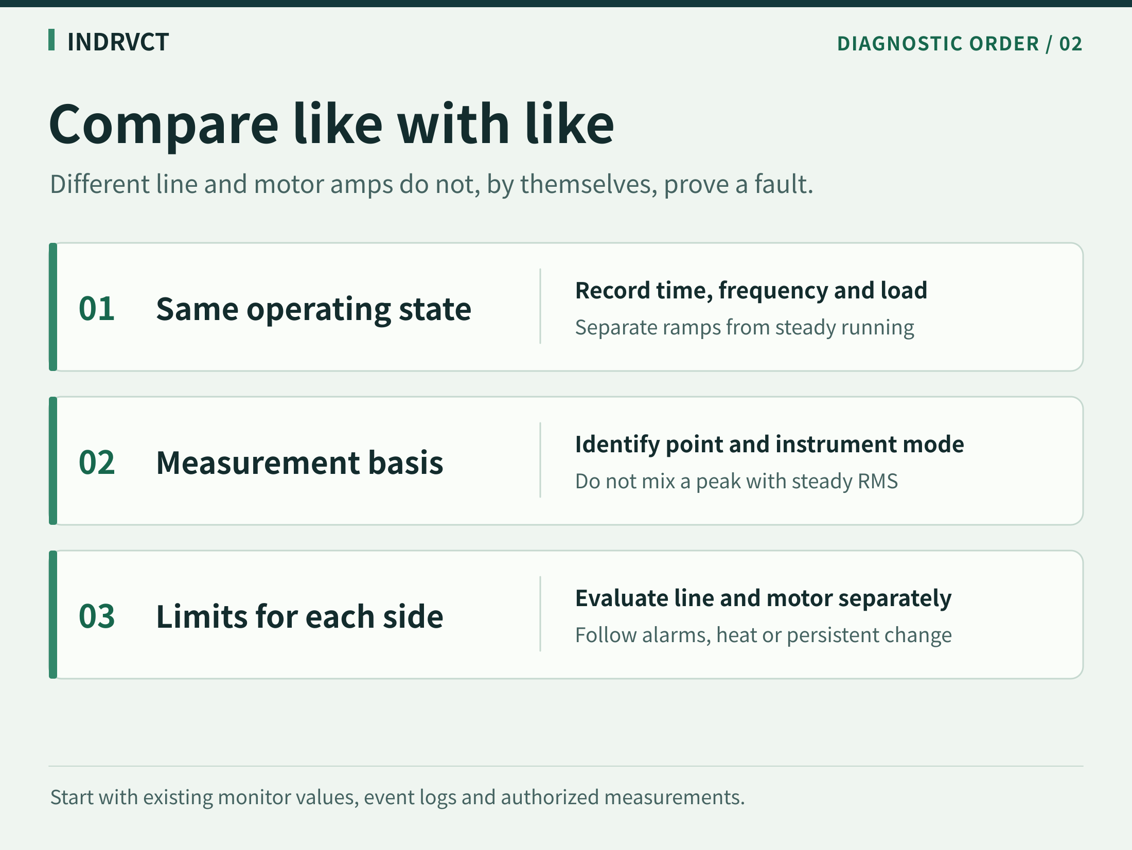
Second, align the type of reading and the measurement boundary. Verify that a supply-side reading refers to this drive rather than all loads on a feeder. For the motor-side value, identify whether it came from the drive monitor or an authorized instrument reading and make sure the records are comparable. A stable discrepancy between two instruments under the same conditions is initially a measurement question. An abrupt change in the same monitor on the same load is a different lead.
Third, follow the evidence to the correct side. High input current or a persistent, unexplained difference between input phases calls for a supply-side review against the installation requirements and previous records. Unusual output current with the same mechanical load calls for checking process load, motor data, thermal behavior and the motor circuit. A trip, abnormal temperature or a persistent departure from baseline deserves investigation even if the numerical relationship between input and output seems familiar.
| Observation | What to check next |
|---|---|
| Input is lower than output at a stable low-speed point with no abnormal symptoms | Verify the operating state, load and side-specific limits. The difference alone need not be corrected. |
| A feeder display and the drive monitor diverge during a ramp | Compare their time windows and what each measurement includes. Repeat the comparison using synchronized records. |
| Motor-side current rises at the same recipe and speed | Review mechanical load changes, motor configuration, phase records where available and temperature trends. |
| Incoming current stays high or changes after a supply-side modification | Review the source, other feeder loads and the applicable drive input limits with the responsible electrical engineer. |
Use the Correct Rating for the Decision
Motor-side continuous current helps assess whether the motor and drive are within their allowed duty. It is not a value to copy into an upstream protection schedule. Supply conductor and protection selection depends on the relevant drive input data, installation requirements and local rules. Likewise a low incoming reading does not show that a slowly turning motor is cool enough. Keep the rated values, actual measurements and permitted duty distinct in the commissioning record.
Frequently Asked Questions
Is lower VFD input current than output current a fault?
Not on its own. It can occur during normal steady motoring because effective voltage, power factor and the kind of current are different on each side. Check the load, instrument basis, alarms and the applicable limits.
Can I use input and output amps to calculate energy savings?
No. Amps measured on different sides are not comparable real power values. Evaluate real input power or energy over a comparable operating cycle, with the measurement boundary and production output held consistent.
Why do a clamp meter and the VFD current display disagree?
The readings may represent different time windows or current components. Check the point, measurement mode and instrument suitability for inverter-fed circuits before treating the difference as equipment damage.
Which details help when I contact support?
Include the full drive model and motor nameplate, the supply and motor-side measurement locations, how the readings were obtained, load and frequency at the time, and any alarms or thermal changes. If available, send a good and a bad trend from the same process condition.
Get Help Interpreting Your Current Readings
If the question is about drive selection, start with the INDRVCT AC drive range and collect the motor and supply requirements separately. For an abnormal change on an installed system, send the time-aligned record and the full model to INDRVCT technical support for a more useful review.