VFD Motor Overheating at Low Speed: A Practical Diagnosis
- 2026 Aug 31
Diagnose VFD motor overheating at low speed. Check cooling airflow, load current, motor data, mechanical condition, duty cycle and temperature trends.
A motor can overheat during variable-speed operation even when the VFD does not show an overtemperature fault. These are different conditions: the drive monitors its own power electronics and heatsink, while the motor has separate thermal limits, cooling paths and protection.
The most common low-speed risk is simple. A self-cooled motor usually has a fan on its shaft. When speed falls, fan speed and airflow also fall. If the application still demands substantial torque, the motor continues producing heat while losing cooling capacity.
That does not mean every case of VFD motor overheating is caused by low-speed cooling. Mechanical overload, incorrect motor data, unsuitable voltage-to-frequency settings, excessive torque boost, blocked airflow, long acceleration, frequent starts or a damaged motor can create similar symptoms. The correct response is to diagnose the system in a controlled order.
First, Separate Motor Temperature From Drive Temperature
Ask which component is actually hot and which protection operated.
A drive overtemperature alarm points to the VFD heatsink, cooling fan, cabinet airflow, ambient temperature, switching losses or drive loading.
A motor thermal trip or hot motor frame points toward motor load, cooling, parameters, voltage quality, mechanical condition or duty cycle.
A drive overload or overcurrent trip is related to output current and torque demand, but the motor may also be heating.
Record the exact event, time, speed, current and temperature before resetting. “The inverter is hot” is not enough; measure the drive, cabinet and motor separately.
Why Low Speed Reduces Motor Cooling
Many general-purpose induction motors use a shaft-mounted external fan. At lower motor speed, that fan moves less air over the frame. The motor’s allowable continuous torque may therefore need to be reduced unless the motor manufacturer provides another loadability curve or independent cooling.
The risk is highest when these conditions occur together:
continuous low speed;
high or constant torque demand;
a self-ventilated motor;
high ambient temperature;
restricted airflow or dirty cooling fins;
frequent starts, reversals or braking;
an enclosure or machine guard that traps hot air.
Variable-torque loads such as many centrifugal fans and pumps often require much less torque as speed falls. Constant-torque loads such as conveyors, mixers and positive-displacement machines can remain demanding at low speed. Load type is therefore part of the thermal diagnosis.
Do Not Guess a Universal Minimum Frequency
There is no safe universal rule such as “every motor can run continuously at 10 Hz” or “below 20 Hz always needs a blower.” The answer depends on the motor’s design, cooling method, frame, insulation, load torque, ambient temperature and duty cycle.
Use the motor manufacturer’s variable-speed loadability data when available. If the application requires continuous high torque at low speed, consider independent forced ventilation, a motor designed for variable-speed duty, a different mechanical ratio, or a larger motor after engineering review.
Raising the minimum frequency can protect cooling only when the process can accept the higher speed. It is not a substitute for understanding the load.
Step 1: Build a Temperature and Operating Trend
Measure rather than relying on touch. Record:
motor frame temperature at consistent locations;
winding sensor data when available;
ambient temperature near the motor;
output frequency and actual speed;
output current and load percentage;
run time before temperature stabilizes or trips;
process load, valve position, material flow or mechanical state.
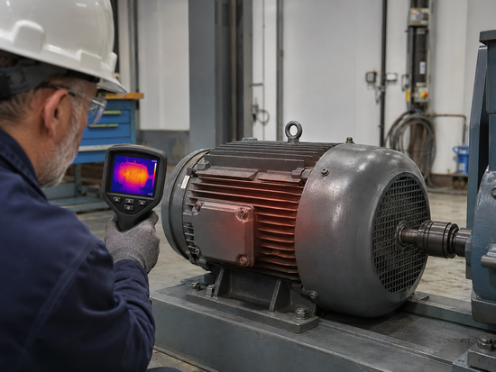
One thermal image can find hot spots, but a time trend shows whether temperature is stable or still rising. Compare similar operating cycles, not unrelated snapshots.
Stop the test if temperature, sound, vibration, smell or current indicates unsafe operation. Temperature limits must come from the motor documentation and protection design, not from a generic surface-temperature number.
Step 2: Compare Current With the Real Motor Rating
Check the motor nameplate current and the current displayed or measured under the actual load. Do not compare only kW values.
High current at low speed may indicate excessive mechanical torque, an incorrect motor connection, wrong motor data, unsuitable control setup or too much low-frequency voltage boost. Normal-looking average current does not completely eliminate thermal risk: reduced cooling can still allow temperature to rise over time.
If one phase or one part of the motor is much hotter, investigate motor, cable and connection condition with qualified test methods. Do not keep increasing electronic overload settings to avoid a trip.
Step 3: Inspect the Mechanical Load
Before changing drive parameters, verify that the machine turns freely and the load is what the process report claims.
Inspect:
bearings and lubrication;
shaft alignment and coupling condition;
belt tension;
gearbox oil and mechanical ratio;
blocked pump, fan, conveyor or mixer;
product buildup or process pressure;
brake release and check valves where applicable.
A binding bearing can make a motor hot at any speed. At low speed, the problem may be more visible because cooling is weaker. Separate mechanical torque from electrical control.
Step 4: Verify Motor Data and Control Settings
Enter data from the actual motor nameplate: voltage, current, frequency, speed and power as required by the selected control mode. Data copied from another machine can reduce control accuracy and thermal protection quality.
Review:
motor rated data and connection;
V/F curve or selected vector-control mode;
torque boost or low-frequency voltage compensation;
current and thermal-protection settings;
minimum and maximum frequency;
acceleration and deceleration time;
motor identification or autotuning status;
carrier frequency and any required derating.
Excessive torque boost can cause unnecessary magnetizing current and heat. Too little voltage can produce weak torque and high slip under load. Make one controlled change at a time and record the result.
Step 5: Check the Cooling Path
Inspect the motor fan, shroud, fins and surrounding airflow under safe isolation. Look for dirt, damaged blades, reversed external-fan airflow, blocked guards and hot air recirculating from nearby equipment.
For independent forced ventilation, confirm that the blower runs whenever thermal conditions require it—not only when the motor shaft is already at high speed. Include fan failure in the machine’s interlock or alarm logic where appropriate.
Do not point an improvised portable fan at the motor and treat that as a permanent design. It can be a diagnostic clue, but the final solution needs documented airflow, protection, wiring and maintenance.
Step 6: Evaluate Duty Cycle and Process Demands
A motor may tolerate a short low-speed positioning move but not hours of continuous low-speed torque. Record the full cycle:
duration at each speed;
torque or current at each stage;
starts, stops and reversals per hour;
dwell periods without rotation;
worst-case ambient temperature;
process jam or overload scenarios.
If temperature accumulates over repeated cycles, the machine may need longer cooling intervals, reduced low-speed torque, forced ventilation, a different motor, or a mechanical redesign.
A Practical VFD Motor Overheating Diagnosis Order
Identify whether the trip or temperature is drive-side or motor-side.
Capture speed, current, temperature, load and time before reset.
Inspect motor cooling and ambient airflow.
Check mechanical load and free movement.
Verify the actual motor nameplate, connection and control settings.
Compare the duty cycle with motor variable-speed loadability.
Test one corrective action at a time and trend the result.
Corrective Options—and Their Limits
| Corrective option | When it may help | What must be confirmed |
|---|---|---|
| Clean fins and restore airflow | Blocked self-cooling path | Safe cleaning, fan condition, recurrence control |
| Independent forced ventilation | Continuous low-speed torque | Required airflow, supply, interlock, environment |
| Adjust minimum speed | Process can run faster | Process performance and mechanical limits |
| Reduce low-speed load | Torque demand is excessive | Production requirement and machine design |
| Correct motor data or control mode | Setup does not match motor | Nameplate, connection and tuning procedure |
| Change mechanical ratio | Motor can run faster for same machine speed | Torque, gearbox and equipment limits |
| Select a variable-speed-duty motor | Wide speed range or severe duty | Loadability curve, insulation, cooling and bearings |
Do not simply install a larger VFD to cool the motor. The drive rating and motor thermal problem are related only through current and duty; a larger drive does not increase the shaft fan’s airflow.
Common Mistakes
Resetting the trip without saving data
The event timing and operating point are valuable diagnostic evidence.
Using touch as the temperature limit
Surface feel is subjective and does not equal winding temperature.
Increasing overload settings
This can remove protection without removing the cause.
Changing several parameters together
You lose the ability to identify which change affected current or temperature.
Blaming the VFD before checking the machine
Mechanical friction, blockage and process overload are frequent causes of high motor current and heat.
FAQ
Why does my motor overheat only at low speed?
In VFD motor overheating cases, the shaft-mounted fan may move less cooling air while the load still requires significant torque. Check the motor loadability data, current, cooling path and duty cycle.
Can a motor overheat even if VFD current is below the nameplate value?
Yes. Reduced cooling, high ambient temperature, repeated duty, waveform-related losses or local mechanical problems can raise temperature even when average current appears acceptable.
Should I install a separate motor cooling fan?
It can be appropriate for continuous low-speed torque, but airflow, environmental protection, power supply, interlocking and motor suitability must be engineered.
Does a larger VFD prevent motor overheating?
Not by itself. A larger VFD does not improve motor cooling or remove mechanical load. Select the drive for current and duty, and solve the motor thermal cause separately.
What information should I send INDRVCT for review?
Send the motor nameplate, connection, VFD rating, operating frequency, current, load type, cycle, ambient temperature, measured temperature trend, cooling method and any fault history.
Diagnose the Whole Motor-Drive-Machine System
Low-speed motor temperature is a system issue, not a single-parameter problem. If you are preparing a variable-speed application or investigating a hot motor, send INDRVCT the operating trend and machine data. A structured review can separate cooling, load, setup and duty-cycle causes before parts are changed.