VFD Overvoltage During Deceleration: A Diagnostic Guide
- 2026 Oct 29
Diagnose VFD overvoltage during deceleration by checking DC bus energy, ramp time, input voltage, load inertia, braking circuit and mechanical conditions.
VFD overvoltage during deceleration usually means the load is returning energy to the drive faster than the DC bus can absorb or release it. A DC bus overvoltage event during stopping is therefore an energy-balance clue. The first question is not “Which parameter clears the fault?” but “When does the DC bus rise, and where should the mechanical energy go?”
This INDRVCT diagnostic guide separates a deceleration event from overvoltage at acceleration or constant speed. It then checks the command, supply, load and braking path in a safe order. Exact alarm names and thresholds vary by model, so use the code and measured values from the installed drive rather than borrowing a code from another series.
What Happens Inside the Drive
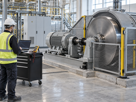
A standard VFD rectifies incoming AC to create a DC bus. The inverter stage then synthesizes variable-frequency output for the motor. During motoring, energy flows from the supply through the DC bus to the motor.
During rapid deceleration, an inertial load can drive the motor faster than the commanded electrical speed. The motor then behaves as a generator. Energy flows back into the DC bus and charges its capacitors. If that energy is not consumed, stored or returned to the supply, DC bus voltage rises until the drive protects itself with an overvoltage trip.
An overhauling load can do the same thing even at constant commanded speed. Examples include a descending load, an unwinding roll, a downhill conveyor or a fan driven by reverse airflow. The timing of the fault is therefore essential evidence.
Make the System Safe Before Testing
Follow the site lockout/tagout procedure. Isolate all energy sources, including external rotation or a suspended load. Wait the specified discharge time and verify DC voltage with an appropriately rated instrument before touching terminals.
A braking resistor can remain extremely hot after stopping. Do not touch it, cover it or measure its resistance while it is connected to an energized drive. If the load can continue to rotate, secure it before disconnecting the motor or braking circuit.
Step 1: Confirm When the Fault Occurs
Record the operating stage, commanded frequency, actual speed, DC bus trend, input voltage, motor current and stop command.
- Fault at power-up or while idle: first suspect high supply voltage, switching surges, incorrect supply or a sensing problem.
- Fault at steady speed: investigate supply events or an overhauling load that continuously regenerates.
- Fault only during deceleration: focus on ramp time, inertia, braking path and mechanical changes.
- Fault after the motor has stopped: review DC bus measurement, incoming disturbances and the exact event log.
Do not change several parameters before capturing the baseline. One change at a time keeps the diagnosis meaningful.
Step 2: Compare the Stop Command With the Mechanical Duty
A shorter deceleration time demands a higher braking torque and transfers energy to the DC bus more quickly. Increase the deceleration time in a controlled test if the process permits. If the fault disappears, the original stop was asking the system to absorb energy faster than its present braking path could handle.
This is a diagnostic result, not always the final fix. A machine may require a specific stop time for production or safety. If a longer ramp is unacceptable, the system needs an energy-handling method sized for the actual duty.
S-curve deceleration can reduce abrupt torque changes, but it does not remove the total kinetic or potential energy. Coast-to-stop avoids commanded electrical braking, yet it is suitable only when an uncontrolled stop is safe and the process allows it.
Step 3: Check Supply Voltage and Disturbances
Measure the input voltage with the machine idle and operating. Compare it with the drive rating and permitted variation. Look for capacitor-bank switching, transformer tap settings, generator regulation, weak distribution systems and other large loads that can create voltage events.
Supply overvoltage and regenerative overvoltage can produce a similar trip but require different remedies. A fault that occurs at random across the operating cycle points more strongly toward the supply than a fault that repeats at the same point in every deceleration.
Step 4: Quantify the Load Inertia and Energy
Rotational kinetic energy is proportional to inertia and the square of speed. Doubling speed produces four times the stored kinetic energy for the same inertia. A flywheel, large fan, centrifuge, roll or high-ratio gearbox can therefore store far more energy than its motor kW suggests.
For vertical or overhauling loads, include potential energy and the time spent lowering. Record motor speed, load speed, gearbox ratio, moving mass, drum or roll diameter, normal stop time, emergency stop requirement and stops per hour.
Mechanical changes matter. A larger roll, replaced pulley, added tooling, freer-running load or reduced friction can make an old deceleration setting fail even though no electrical parameter changed.
Step 5: Inspect the Braking Path
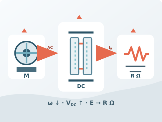
A dynamic-braking system commonly uses a braking chopper to connect a resistor across the DC bus when voltage rises. The resistor converts electrical energy into heat. Some systems instead return energy to the supply through a regenerative unit or share energy through a common DC bus.
If a resistor/chopper is installed, check safely for:
- loose, damaged or incorrectly landed wiring;
- an open resistor or operated thermal protection;
- incorrect resistance for the drive and braking unit;
- insufficient power or duty rating;
- disabled braking function or wrong terminal selection;
- a chopper that never switches despite a rising bus;
- enclosure overheating around the resistor.
Do not substitute a lower-resistance part to obtain “stronger braking.” Too low a resistance can exceed the chopper current limit and damage equipment. Resistance, continuous or short-time power, thermal protection, mounting and duty cycle must all be verified.
Step 6: Choose the Correct Remedy
Lengthen the deceleration time
Use this when the process allows a longer stop and the fault is caused by an aggressive ramp. Confirm the machine still meets production and safety requirements.
Add or correct dynamic braking
Use a compatible chopper and resistor when stops are intermittent and the calculated energy and duty fit dynamic braking. Account for resistor temperature and enclosure ventilation.
Use regenerative equipment
Frequent braking, continuous overhauling or high energy may justify an active regenerative unit. It can return energy to the supply, but harmonic, protection and grid requirements must be engineered.
Modify the mechanical or process profile
Reduce peak speed, divide the stop into controlled stages, coordinate upstream equipment or remove unexpected back-driving. A control change can reduce the energy peak without simply hiding the fault.
Address the supply
If the fault is caused by high incoming voltage or switching events, correct the distribution issue. A braking resistor is not the remedy for a supply that is already too high.
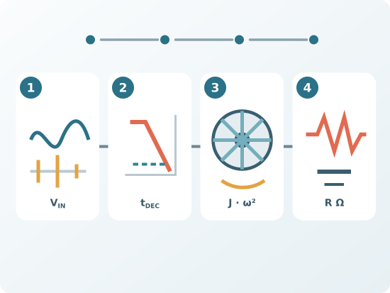
Diagnostic Order at a Glance
- Preserve the event data and identify the exact operating stage.
- Make the machine safe and verify DC discharge.
- Check input voltage and the DC bus trend.
- Test a longer deceleration time if the process permits.
- Compare actual inertia and speed with the original design.
- Inspect resistor, chopper, wiring and thermal protection.
- Calculate energy and duty before changing hardware.
- Retest one change at a time and document the result.
Common Mistakes
Resetting repeatedly without preserving the event
Repeated resets erase context and can overheat braking components. Save the fault time, stage and measured values first.
Increasing drive kW without calculating energy
A larger drive may have a larger DC bus, but it does not automatically provide a path for repeated regenerative energy.
Assuming every overvoltage fault needs a resistor
High supply voltage, wrong transformer taps or external back-driving require different actions.
Checking only resistor resistance
The correct ohmic value is not enough. Duty, energy, thermal protection and mounting determine whether the resistor survives.
Ignoring mechanical changes
New tooling, a larger roll or changed gearbox can alter stored energy and stop behavior.
FAQ
Why does a VFD trip on overvoltage only when stopping?
The motor is likely returning kinetic or potential energy to the DC bus during deceleration. If the bus cannot release or return that energy quickly enough, voltage rises and the drive trips.
Will increasing deceleration time solve the fault?
It often helps by spreading the energy over more time. It is not a universal final solution if the process requires a short stop, the load continuously overhauls or the braking circuit is faulty.
What are common braking resistor fault symptoms?
The drive may stop normally at light load but trip during faster or heavier deceleration. An open thermal switch, visible damage, loose wiring or a resistor that never warms can be clues, but testing must follow the drive and resistor safety procedure.
Can I install any braking resistor with the correct resistance?
No. Minimum resistance, pulse energy, average power, duty cycle, insulation, thermal protection and the chopper rating must all be compatible.
Why did the fault start after a mechanical modification?
The modification may have increased inertia, speed, moving mass or back-driving torque. Because kinetic energy rises with speed squared, a modest speed increase can materially change braking demand.
Send the Event, Not Just the Alarm Name
For INDRVCT technical support, provide the complete drive nameplate, supply voltage, motor data, load type, maximum speed, deceleration time, braking components and the operating stage where the trip occurs. A short video of the speed, current and DC bus trend can make the diagnosis much faster.