VFD Undervoltage Fault When Another Motor Starts: What to Check
- 2026 Nov 12
Trace a VFD undervoltage fault by comparing supply events, feeder voltage and DC bus records. Learn what to log before you reset or replace a drive.
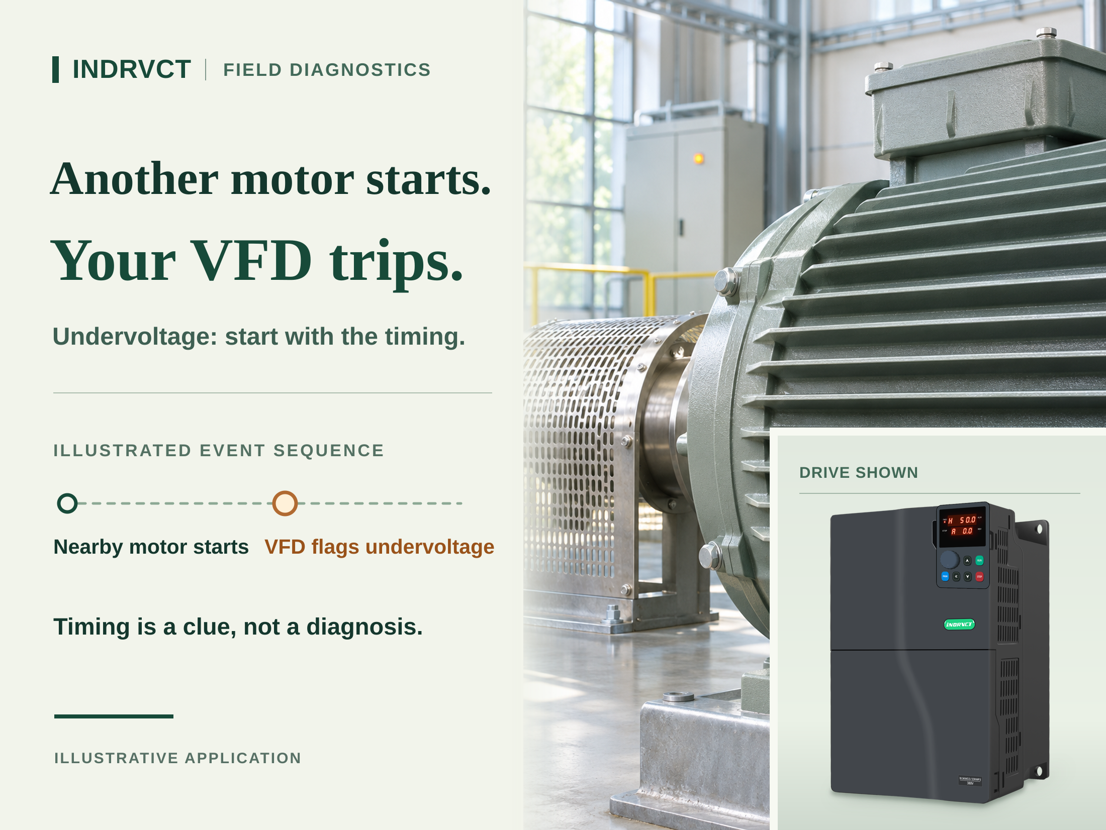
When a drive trips as another motor starts, compare the event time and the input supply before replacing the drive. A VFD undervoltage fault tells you that a monitored voltage fell below the drive's operating limit. It does not, by itself, say whether the disturbance came from the plant supply, the drive's own feeder or the drive. A normal panel reading a minute later cannot rule out a short voltage sag.
Start with records that can be collected without opening energized equipment. Match the drive event, the other machine's start signal and any existing power quality record. The aim is to find where the voltage changed, not to force the fault to happen again.
Why a Supply Dip Can Become a DC Bus Fault
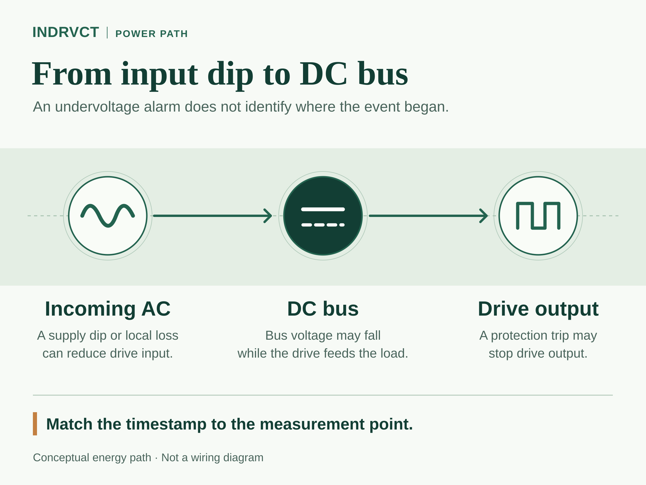
In a typical AC-input drive, the input stage supplies a DC link, which in turn supplies the output inverter. During a disturbance, the DC link can fall as the drive continues to feed the motor. Whether the drive trips depends on the disturbance, the actual load and the behavior of that drive. The message may describe DC bus undervoltage even though the original change was on the AC side.
An incoming voltage sag is only one possibility. A bad connection or a problem in a dedicated feeder can cause a drop closer to the drive, especially as load changes. In some cases an input phase is lost, or a contactor opens before the undervoltage event because another device has already removed the supply. If input evidence stays healthy at the drive throughout a well-captured event, the input stage, DC link or sensing may need further investigation. None of these should be diagnosed from a fault label alone.
Step 1: Preserve the Timeline Before Clearing the Fault
Write down the exact message and machine state: running steadily, accelerating, stopping, or powering up. Export available drive fault history and PLC or equipment events using their normal interfaces. Record the equipment that started, whether it shares the same distribution board, and whether other drives or controls showed anything at the same time. Do not assume all displays use a common clock. Note any offset and whether a timestamp is for the trip, the logging event, or the operator's reset.
Save the last available input and DC bus records with their sampling interval and point of measurement. A value captured after reset, an averaged HMI display or a meter at an unrelated panel does not tell you what reached the drive during the fault. If logs show that a safety or process interlock opened a contactor first, investigate that sequence before treating the low voltage message as the initiating event.
Step 2: Compare the Supply, Feeder and Drive Records
Ask qualified electrical personnel to compare records from the upstream distribution point and the drive input over the same time window. Start with installed meters or existing logs. If those are too slow or were not recording, let qualified personnel plan appropriate power quality monitoring under the site's electrical safety procedures. Do not open a live cabinet or probe a DC link as part of routine operator checks.
| Pattern in time-aligned records | First area to investigate | What it does not prove |
|---|---|---|
| The shared distribution voltage and drive input dip together | Common supply, large-load starting or a transfer event | Which upstream component caused the sag |
| Shared supply stays stable, but voltage at one drive input drops | Local feeder, fuses, isolator, contactor or connection | That the drive itself has failed |
| Drive input is healthy throughout a well-captured event, but DC link drops | Drive input stage, DC link or sensing, with qualified service | That a capacitor or any other specific part is defective |
| A contactor opens before the drive reports low voltage | Interlock and shutdown sequence | That undervoltage initiated the stop |
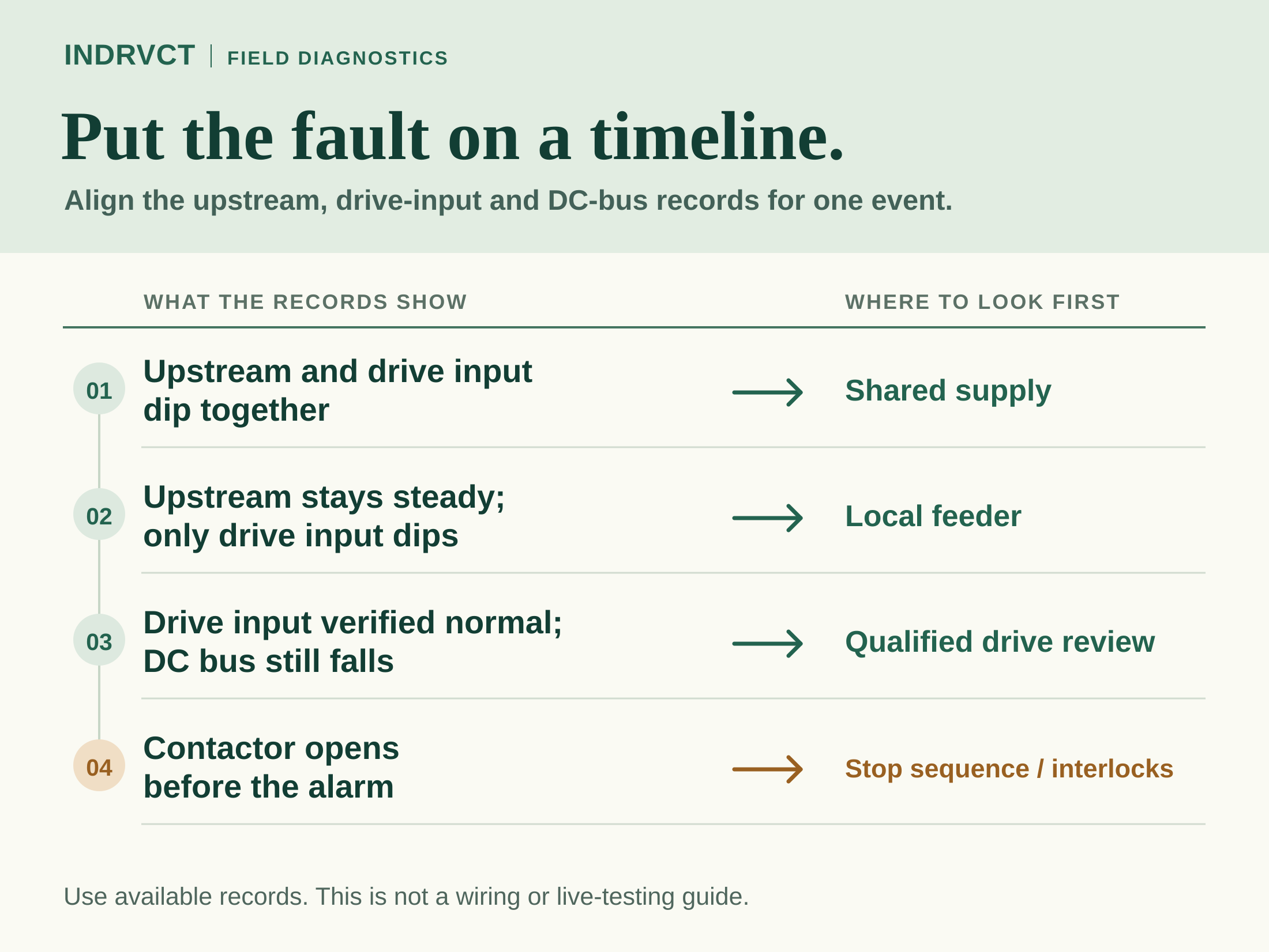
Treat the table as a way to prioritize the next check, not a remote diagnosis. If more than one machine trips, a shared supply disturbance becomes a useful lead, but not all loads react the same way. If only one drive trips, check the evidence at that feeder rather than assuming either a healthy supply or a failed drive. Where input phase loss or imbalance is suspected, the electrical team should review evidence for all phases at the relevant location. One phase-to-phase reading is not a complete record.
Step 3: Match the Corrective Action to the Evidence
For a shared voltage sag, facilities staff can review which loads start together, their starting methods, the supply impedance and any transfer or utility event. Revising the start sequence may be a practical project option, provided the process and safety controls still work as required. Do not treat an increase in drive power rating as a guaranteed fix for a common feeder problem.
For a local drop, arrange a qualified inspection of the relevant circuit after approved isolation, lockout and verification. Stored energy can remain in the drive after the supply is removed. Follow the site's rules for energy control and verification; a dark display is not proof of isolation. If no input disturbance is captured with adequate resolution at the drive and the symptom persists, use INDRVCT service and support to arrange model-specific review rather than opening the drive or replacing parts by trial and error.
Do not lower a protective limit, bypass a safety interlock or enable automatic restart to suppress a repeated